Background

Click any photo in a post to enlarge. To leave a comment, click a post's title or post date.

Sunday, May 3, 2015

Repairs

Would you believe I actually started pricing drivers insurance!  Our current carrier is trying to soak us, so I'm looking into other options.

I also looked into inspections and registration.  I don't want to install all the windows and weatherstripping yet, because it will only have to be removed again when the car is painted.  However, I'd like to get several estimates on the paint job before I pay for painting, and the only practical way to do that is drive it there. . . Turns out that you don't need windows (or apparently a windshield) only wipers.  Apparently, you don't need a speedometer either. . .  Texas also has a 30 day temporary registration that allows you 30 days to get your inspection.

Being this close, reminded me that there are some repairs that needed to happen to systems I'd already installed.

One of these was the clutch master cylinder.  The makeshift cap has continued to leak, so I had to buy a new one.


The only problem is that the only new ones I could find do not have the filler stem.

So I had to solder in the old one. . .I'm not sure what type of metal the new cap is made of, but it did NOT want to accept the solder.  It took many tries to get it to take, but it finally did and has been reinstalled.


I also needed to replace the intake manifold gasket as it had blown out at the rear of the engine and was leaking coolant.  While I had the engine torn down that far, I figured it was probably best to go ahead and replace the head gaskets too, just to make a clean job of it.


I'm glad I did.

Take a look at the photos below and see if you can tell me what's wrong:


Did you notice there are three different hole patterns?

The new head gaskets are identical to the ones I installed last time.  Which means that only a fraction of the coolant chambers are being filled, as the gasket was blocking some of them.  Just as worisome is that fact that the head ports dont match up with the block ports.  Nothing I can do about that, but I can adjust the new gaskets to allow as much flow as possible between the two.  The gasket has an aluminum core, so I had to cut out the new openings with a dremel with router bit.

Incidentally, the same problem was true of the old manifold gasket.  The gasket I installed last time intentionally blocked several of the ports.  In hind sight, that is probably why it blew out - not because of the pressure, but because the manifold head warped slightly due to overheating.


Sunday, April 12, 2015

Eye Surgeon

At the end of the last blog, the nose was back on the car.

As soon as it was though, I had another fit of uncertainty about how to procede.  The next step of the tilt-nose conversion process is to mount the headlight rotation assembly to the metal chasis.  This is what the directions show for the bracket dimensions:


Note that the dimensions are in decimal inches to the thousandth of an inch.  Precision is important at this step, because the hood must rotate closed over top of the installed headlight buckets while lining up exactly flush with the bucket surface and leaving only an 1/8" or so gap around each bucket.  Likewise, once the hood is closed and latched, the headlight buckets themselves need to rotate up out of their "home" in the cowling to their upright and operable position within the same 1/8" gap.

However, every step of the proces to date has taught me that there is NOTHING uniform or reliable about the factory finished dimensions of these vehicles.  Not to mention the fact, that I'm going slightly rogue at this point in attempting to make this transition while still maintaining an all weather daily driver vehicle and therefore attempting to maintain the front wheel well baffles.  I'm an architect too, which means I think I can improve on the aesthetic quality of the design and make it look more "stock".

Sooo,  how to procede when you don't know what it is you're really doing and you need to design brackets that correctly align in three directions (and rotationally)for proper clearance of two different hinged assemblies? Two phrases: guesswork and trial and error (lots of the latter)!

But first, and most important, you put off the decision by working on something else while you build up your courage. . . 

So I began work on some of the interior finishes.

I rebuilt the hardboard door panels and mounted the front speakers.

I decided I wanted to add arm rests to the doors, so I carved some.  I had to make revisions to the door frame itself to mount them (more on that next time).


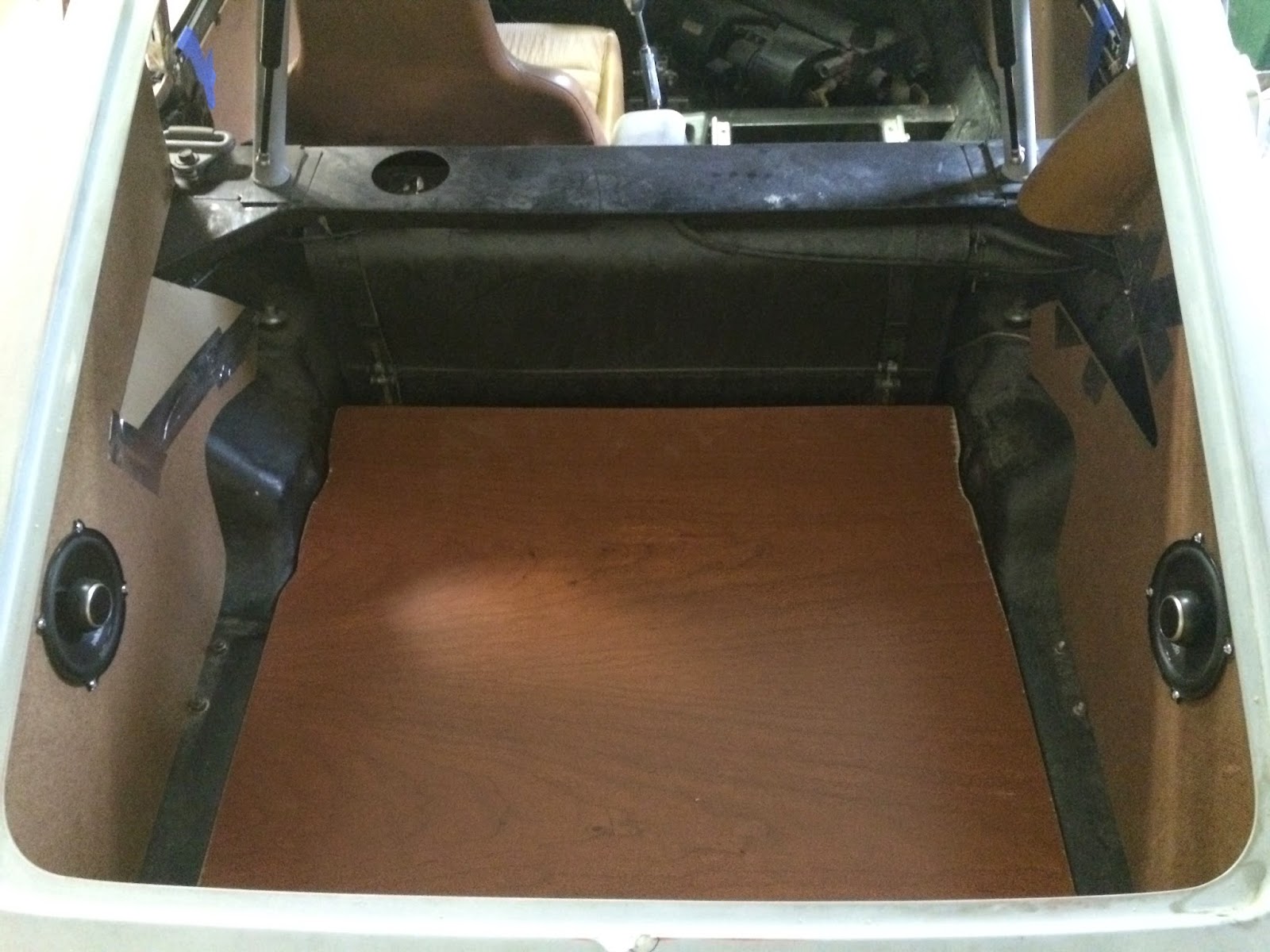
Then I did similar hardboard work for the trunk rear and side panels and cut a new trunk floor.


It took me four tries to figure out how to resolve the complex geometry just behind the gas tank.  The original hardboard was so waterlogged, warped and bent, it was impossible to tell, but I think it was originally press formed or bent somehow into arch shapes.  I eventually, just cut a wedge shaped notch and used a thinner, more pliable card stock to warp between the surfaces.

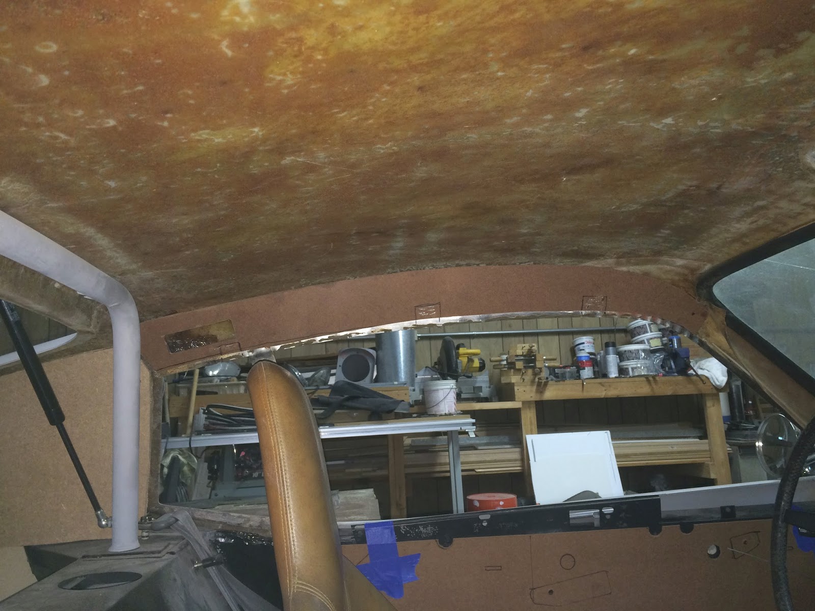
I also installed new hardboard over the doors.  These were also tricky because it involved gluing small hardwood spacer blocks at critical locations to recieve mounting screws through the exterior stainless steel trim.


I still wasn't feeling confindent in tackling the headlights, so I installed a set of used seatbelts from a Honda Civic donor:


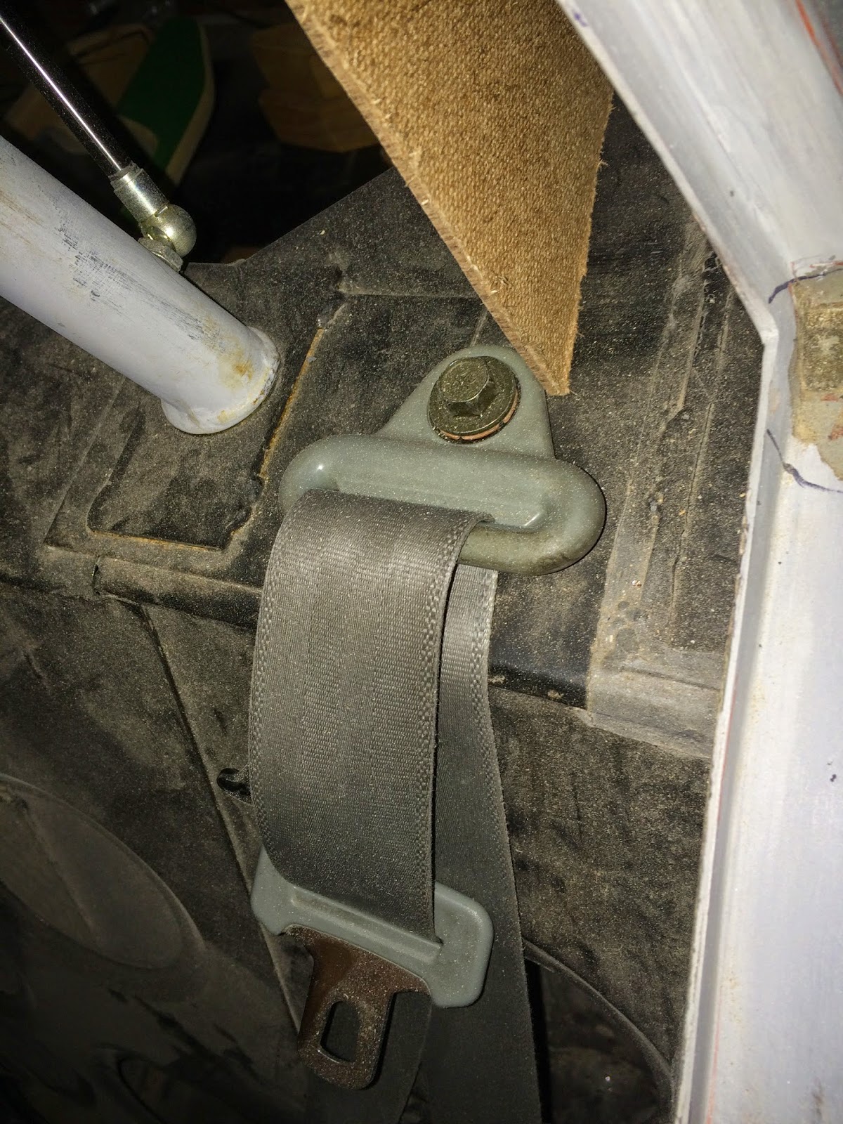
The fixed, and shoulder connections bolted right in to the original points.  The retraction assemblies took a little more finaegeling.  However, they tucked in fairly nicely into existing bulkead holes when expanded a little at the top, and with a custom clip angle bolted to the bottom that matches up with one of the rear suspension bracket bolts that is conveniently in this location.

By this time, I was starting to feel more confident again, but I knew proper alignment of the hood would be a big piece of the puzzle, and the more consistency throughout the process I could muster, the better.  Therefore, I finished the final installation of the hood latches to literally lock the hood in position for better measuring/guesswork.

First I cut two curved wedges of hardwood and embedded them in two layers of fiberglass matt in the corners of the hood just in front of the windshield.  Then I marked and installed the two latch clasps with short pan head screws.


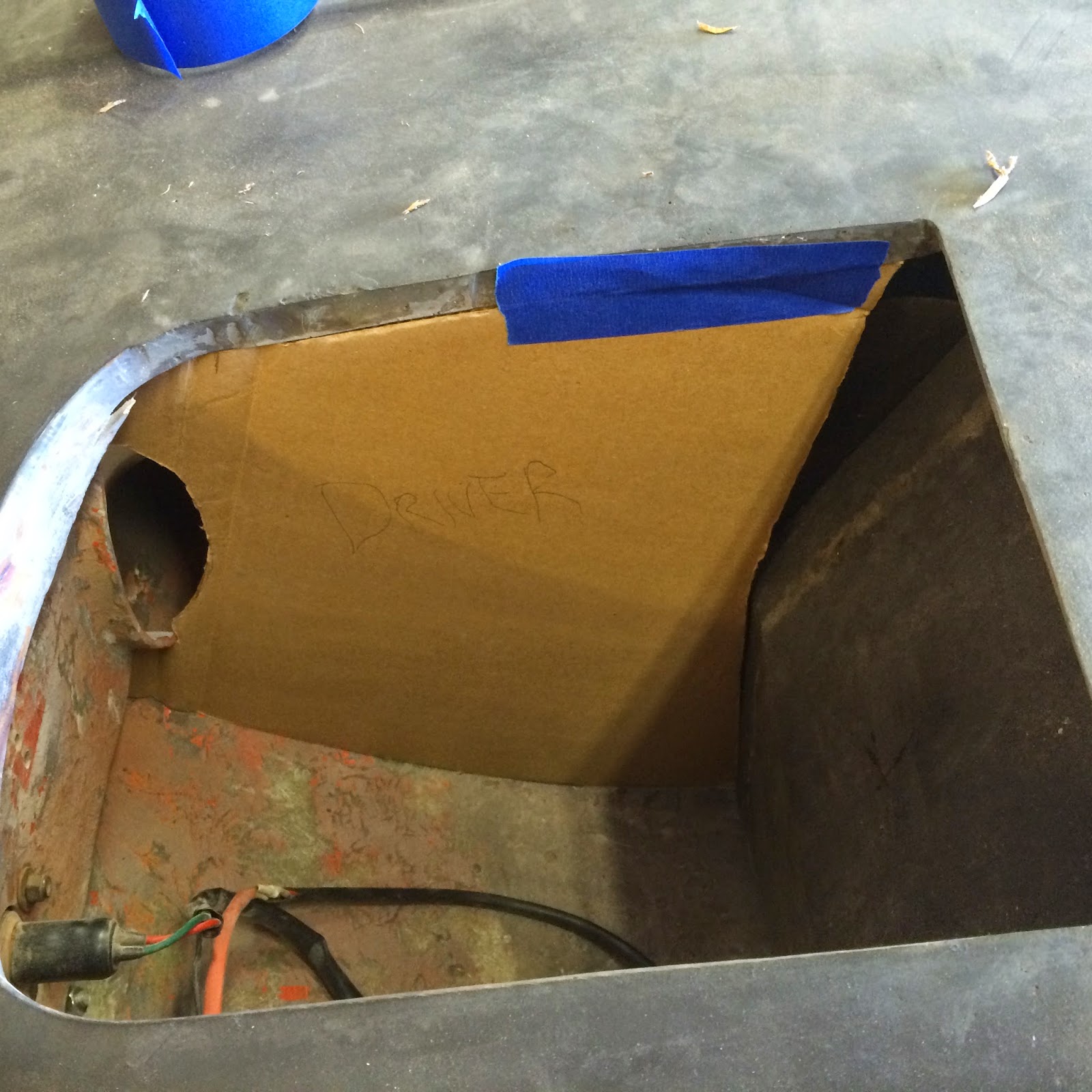
Since I have two latches, and two cables, but only one release pull, I had to connect both cables, with only just enough slack to operate the latches (about 5/8" total travel) inside the drivers side door pillar through these two 3 1/2" holes.


A full day of frustration and cursing followed. . .

But eventually, by blind feel, I was able to get it all assembled and working.  This is what it looks like from below:


The two cables are at the top left.  I fabricated a new bracket to hold the ends of the cables in a fixed position while aligning both with the pull rod (fabricated in the last blog - center).  I brazed a nut to the end of the pull rod and attached two connection anchors to it using a small bolt.  The ends of the cables were then carefully cut to the proper length and attached to the pull rod anchors using electrical crimp connections.  (The vertical wire at center is the power for the door switch for the interior lights.)

The amazing thing is: It works!

But what about those pesky headlight brackets!

Well, they're not quite completed yet, but they have been fabricated, fitted, tested, and partially removed again for refinement, and: 
  • the tilt rod is attached again to the vehicle
  • the spring-loaded headlight rotation arm does operate correctly
  • the hood does clear the headlight buckets and does latch securely
  • I was able to retain the front wheel well baffles
  • with a little grinding, filing, sanding, and paint I think they'll even look attractive!
I'll show the finished product next blog, but here's a sneak peak:


Wednesday, December 24, 2014

Nose Job Hardware

Time to re-attach the nose to the body:

After some final finagling to ensure everything was aligned as closely as possible, the hinges were welded to the steel frame and bolted to the fiberglass.  Only then was I able to tell if it would actually work as expected.  I had to make a few minor modifications to the braces that are within the drainage channel.  I also had to cut the flaps just in front of the doors so that their curvature does not interfere with the rotation of the braces on the sides of the hood.  This is what it looks like in place and operational:


The hinge connections are working properly.  However, there is enough rotational force on the hood that the stop braces (which keep the nose from flipping completely over and smacking on the floor) were twisting under the force.  So I added reinforcing in two directions. . .


That kept the braces from bending, but now it was twisting the frame to which they were attached. 

Time for Plan B.  An angle welded to the hinge itself prevents them from turning too far.  This approach required a little trial and error to get just the right length on the angles so that they stop the hood at the desired location and both sides are aligned, but it is a much simpler, elegant, and reliable solution.


Next dilemma: how to secure the hood when closed?

I took a field trip to the local pick-and-pull yard and found two Honda Civic donors with trunk latches that looked like they would do nicely.  They are both relatively compact, and will fit between the outer and inner bodies just above and beyond the top door hinges.    I had to remove a small bend in each, and trim them a bit to fit the desired locations.  Here's what they look like installed.


Passenger                                                                                                                                               Driver

The original hood release pull was missing - so I made my own.  Not bad, I think.  


The original was mounted way at the back of the firewall.  The new location is just inside the driver side door.  I still need to figure out the final connection of the cables to the pull before it is operational.  I will also need to glass in wood mounts to the hood for the hook side of the latches.

The original configuration of the hood included baffles in front of the wheels to keep dirt and water off of the headlights when they are in the down position.  I wanted to maintain that functionality, but the rotation of the hood now rotates the bottom face of the cowling through that plane.  I needed a solution that utilized a flexible membrane similar to a "mud flap".  A pair of cheap black rubber floor mats from the auto parts store worked nicely after trimming back the bottom of the original steel baffles.
                                                                                   
Wheel Side
Headlight Side
Note in the photo above (left) that I had to drill holes through the new baffles for the wiring for the front end lights.  The holes are just above the hinge point, so even though the hood rotates +/- 90 degrees, there is little movement of the wires themselves.


Monday, December 1, 2014

Nose Job - Second Surgery

The reinforcing fiberglass work is done!


It may not look like much, but the photo above represents about 14 hours of work.  The fiberglass did not want to cooperate for much of the work.  It kept forming bubbles and/or edges that would peel up, requiring hours of supervision to force all the defects back into shape until the final "set" of the epoxy.  Each of the ribs got three layers of fiberglass.  I also added a layer over the lip between the original "hood" and the nose to lock it in permanently.  With the ribs completed, the nose can now fully support itself.

This is what it looks like back on the car:


As you can see by the photos below, the vertical position is not quite right at the rear corners.  However, there is enough flexibility still in the nose that these can be forced into correct alignment with minimal pressure.  I will need to figure out how to install hood catches such that it holds the corners down and in alignment when latched. As mentioned earlier, the passenger side gap is optimal, but the driver side gap is very large, and will need to be adjusted later.

All in all, I am very pleased with the results!  The process was nerve-wracking as I had no way of knowing if the final shape would be correct until the final batch of fiberglass had set!  I also did not know if the final shape of the ribs would clear all the important bits.  Most of the clearances are not exacting, but there are a few corners where there is only a 1/4" or so clearance on each side of one of the ribs to the face of the windshield drainage channels.


While I was waiting for resin to cure, I also added a new chrome plated support plate and pneumatic struts to the rear hatch window.  For my model vehicle, originally, there was only a manual support rod on one side to hold the glass open when in use.  As the glass is quite heavy, this was less than convenient.  As you can see, the new struts easily support the weight of the window.  The bottom end of the struts have studs that are threaded into newly drilled and tapped holes in the roll bar.


Tuesday, November 18, 2014

Nose Job - Second Surgery Prep

With the bulkheads in place, the next step is to add reinforcing ribs to the bonnet.


The steel angle in the foreground helps to ensure that the "wings" near the doors will be in the correct position once the fiberglass dries.  The ribs are once again made from foam core and are 1/2" wide and approx. 1" tall.  They are held in place with contact cement until the fiberglass dries.

I also need to add some mounting supports for the new auxiliary fog lights.  With the baffles in place I can build off of those.  The plywood will be encased in fiberglass when it's done.   I have not actually applied the fiberglass yet as it has been very cold in the shop the last few days.


Also needed are the hinges themselves.  The rough fabrication has been completed.  The top side of the hinges will "sandwich" the fiberglass and bolt through it.  The tube steel side of the hinge will be welded to the existing metal frame just below the fiberglass nose.  The brackets in the middle are the stops that will be bolted to each side of the metal frame to keep the nose from rotating too far.  After a test fit and attachment of the tube steel to the frame, I will paint these before final assembly.


The nose needs to rotate up and down, and so do the headlights, but independently of each other.  Therefore, the next set of brackets needed is to attach the headlights armature to the metal frame instead of the fiberglass.  The following photo shows how the armature was originally attached to the fiberglass.

The "tabs" on the fiberglass are no longer needed or wanted, so they have been cut off.


Now similar supports need to be created on the steel unibody. I've fabricated them so they fit just behind the existing splash guards at the front of the wheel wells.

Driver Side

Passenger Side
The passenger side has to fit around a bump-out for the alternator, so the bracket had to be curved in two directions.


To complete the brackets,  I'll need to fabricate four "L" shaped attachments that will actually fit around the armature pipe.

Tuesday, November 11, 2014

Nose Job - First Surgery

I've decided to add a tilt-nose conversion to my car so that getting to all the under-hood parts is a little more manageable.  It will increase access to the engine bay from this. . .


To this!


The first step is to check that all the body panels are fitting properly and/or that you know they will fit.  The rear body was attached and the door skins installed to check the gaps.


As you can see, the passenger door fits pretty well at the strike side.  I decided to tweak it a bit, however to get the gaps even tighter.

The driver side did not.  There were large gaps.  I've already ground down the edge of the door to accept a fiberglass extensions.

This is what they look like now.
Passenger
Driver
Next I set the nose in place to check the front gaps.  They are a little harder to gauge as there is some warping to the fiberglass which keeps the nose assembly from staying put on both sides.  However, they appear to have too much gap.  I will adjust the final gap later once the tilt mechanism is complete.

The first step of the actual face-lift procedure is to permanently attach the original "hood".  I secured the hood from the bottom side with temporary screws.  I'll remove them and add a bridge of new fiberglass over the transition later.


Then I ground down a lip on the top surface of both the hood and the body and fiberglassed the hood into place.  Bondo and primer complete the transition.  I've cut a new opening in the "scoop" so that it is actually functional.  I'll mount a screen behind it later.


The next step is to reinforce the fiberglass nose so that it can withstand all that moving around without breaking.  It is designed to be supported by the metal unibody frame, so it needs some new bulkheads and other supports to be rigid enough to handle the new stresses.

I cut new baffles out of cardboard for each side to fit in the front of the nose beside the headlight buckets.  This is the most critical upgrade as it is where the hinges will be mounted and the weight of the entire nose supported when it is done.

(Note that I notched around the auxiliary light sockets - I've got a new set of aftermarket fog lights that will be going in there later.

The patterns were then transferred to 1/4" foam core, and coated with two layers of fiberglass matt, which provides a temporary non-structural framework for the fiberglass.  I had to brace the tall side of the assemblies until the fiberglass dried.